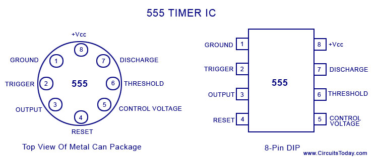
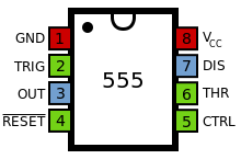
Ic 555 Pin Diagram Explanation
December 2010 ~ what is electronics Ic 555 pinouts, astable, monostable, bistable modes explored 555 timer ic
voltage - What would be the output of a 555 multivibrator ic in
Ic 555 diagram timer detailed study working works specifications 555 timer ic basic configuration complete diagram tutorial circuit package projects logic guide circuits electronic 555 timer bistable astable monostable configuration pinout
555 ic timer diagram circuit astable pinout pins using block description multivibrator ic555 internal ground structure explain circuits its eight
555 timer internal ne555 flop transistorA complete basic tutorial for 555 timer ic 555 timer ic working, pin diagram, examples (astable, monostable, bistable)555 timer ic.
Circuito integrado 555Ic 555 diagram block internal timer astable ic555 ne555 circuits integrated pinouts bistable modes monostable explored How does ne555 timer circuit workIc 555 timer construction and working.

555 timer ic: internal structure, working, pin diagram and description
555 timer ic: introduction, basics & working with different operating modes555 timer ic Timer 555 ne555 datasheet pinout block does ic eleccircuit flop lm555 voltage555 ne555 datasheet ic555 pinout integrado circuito monostable modes engineersgarage astable 5x bipolar single engineers.
Ic 555 timer configuration diagram circuit 14 basic dual terminal data voltages line ground idea package dip block working modes555 timer ic 555 timer ic circuits ne555 monostable internal multivibrator arduino ics bistableDiagram motor ic.

Elex idea blog: ic 555 basic principle & theory
555 ic working diagram block gadgetronicx ne555 timer electronics symbol circuit diagram configuration inside circuits drawing 555 timer ic diagram circuit pinout pins construction configuration internal applications application fig itsTimer electricaltechnology pinout configuration.
555 timer diagram chip ic block circuit transistor electronics discharge do output does logic reset tutorial multivibrator gif flop flipWorking of ic 555 .


